CONTROLLER KIT
111 Horsepower Increase
The 390 Controller Kit uses all the good pieces from 390 hnpressor Kits, except for the addition of a stiffer-grind hydraulic cam. There's also a couple of options. The first is "pop-up" pistons to increase the compression ratio, when the 428 heads are installed on a 390 block. This eliminates having to mill the heads, which is especially handy if you plan to drop in a mechanical cam later on. The second is an optional Stage 5 that has the pieces to convert your 390 into 410 cubes of mean, get out of the gate go-power. Stages 1 and 3 remain unchanged, so we'll revisit Stages 2 and 4.
STAGE 2 (Revisited)
To Add 48 Horses With Big
Street'n Strip Hydraulic Cam
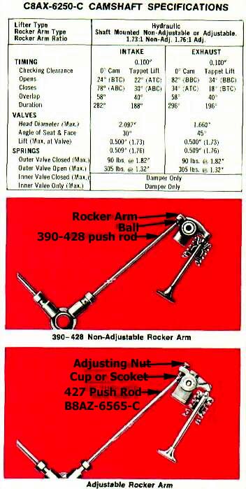
You can really give your 390, with the 735 cfm Holley on top, somewhere to go with HYDRAULIC CAM C8AX-6250-C. It adds 48 bhp @ 5500 rpm over the stock 390 4V cam. It works best with a stick shift, but can be coupled to an automatic. For maximum strip performance with an automatic, install a high slip angle convertor (non-Ford Part). This may be a little rough on the street, but it helps make you a weekend winner. Continue to use the Impressor Kit valve train pieces, unless you install the optional "pop-up" pistons in Stage 4. Then, instead of the 0.060" shorter 390 push rods, install the standard length 390 push rods.
NOTE: If you want to get a head start on your Dominator Kit, and increase valve lift from 0.500" to 0.509', install the 427 ADJUSTABLE ROCKER ARMS B8A-6564-B (16 req'd). Their 1.76 ratio compared to the stock 390's non-adjustable ratio of 1.73 accounts for the additional lift. You also must use 427 PUSH RODS B8AZ-6565-C (16 req'd). They have a ball on the tappet end and a socket or cup on the rocker arm end into which the adjusting screw seats. 390 push rods have a ball on both ends.
If you use the non-adjustable, shaft-mounted rocker arms, correct valve train clearance is designed into the system. However, if you use the adjustable, shaft-mounted rocker arms with hydraulic lifters, the following adjustment must be made to assure the lifter operates in the middle of its travel.
Position the No. 1 piston on TDC at the end of the compression stroke. Bleed the hydraulic lifter for each valve to the fully compressed position. Adjust the locking nut on the end of the rocker arm to obtain a clearance of 0.110"-0.210" at the valve. Repeat this procedure for each cylinder by turning the crankshaft a 1/4 turn at a time in the direction of rotation, while adjusting the valves in the firing order (1-5-4-2-6-3-7-8).
Operate the engine and check for rough engine idle or noisy lifter(s). Tight valve clearance causes rough engine idle. Loose valve clearance causes noisy lifter (s).
Hydraulic Cam C8AX-6250-C

STAGE 4 (Revisited)
For Optional "Pop-up" Piston
That Adds 10 Horsepower
If you plan to install the Dominator Kit later, you can get a head start by using the "pop-up" pistons discussed earlier, in your Controller Kit at this point. They will increase the compression ratio to 10.7:1 without having to mill the 428 cylinder heads. By not milling your heads now, you won't have to replace them later if you go the Dominator route. Install the standard 390 PUSH RODS C4TZ-6565-B (16 req'd) with the non-milled heads, "pop-up" pistons, the regular steel gaskets that come with the heads, and hydraulic cam. The "pop-up" pistons give 10 more horsepower at 5200 rpm than the milled heads (21 bhp) for a total increase of 31 bhp @ 5200 rpm.