Ignition Switch Replace on Fairlanes

-
1963-66 Fairlane
1. Disconnect battery ground cable.
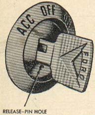
2. Turn ignition key to "ACC" position, Using a paper clip, slightly
depress release pin and turn key counter-clockwise.
Then pull key and lock cylinder out of switch.
3. Press in on rear of switch and rotate switch 1/8 turn counter-clockwise
(as viewed from terminal end).
Remove bezel, switch and spacer.
4. Remove nut from back of switch. Re-move accessory and gauge feed wires
from accessory terminal of switch. Pull insulated plug from rear of switch.
5. If a new ignition switch is to be installed, insert a screwdrive into lock opening
of switch and turn slot in switch to full counter-clockwise po-sition.
6. Connect insulated plug with wires to back of switch.
Position accessory and gauge wires on switch stud and install retaining nut.
7. Position spacer on switch with open face away from switch.
8. Place bezel, switch and spacer in switch opening. Press switch toward
instrument panel and rotate it 1/8 turn to lock it in position.
9. If new lock cylinder is to be installed, insert key in cylinder and
turn it to "ACC" position. Place lock and key in switch, depress
pin slight-ly with a paper clip and turn key counter-clockwise.
Push lock cylin-der into switch.
10. Connect battery cable and check switch operation.
1967 Fairlane
1. Disconnect ground cable from battery.
2. With ignition key, turn switch to the left while inserting a
fine wire pin in hole beneath key slot.
3. Slightly depress pin while turning key.
This will release lock cylinder from switch.
Pull out lock cylinder with key.
Remove switch bezel nut and lower switch from instrument panel.
Re-move accessory and gauge feed wires from switch, also insulated plug.
Reverse procedure to install.
In-sert key and turn to accessory posi-tion.
Place cylinder and key in switch.
Depress pin slightly while turning key counterclockwise.
Push cylinder into switch and remove pin.
1968-69 Fairlane
1. Disconnect battery ground cable.
2. Insert key and turn switch to ac cessory position.
Insert a wire pin in hole in switch.
Slightly depress pin while turning key counterclock- wise past the accessory position.
This will release lock cylinder. Pull out lock cylinder with key.
3. Remove bezel nut. Lower switch from instrument panel and remove accessory wire nut.
Depress tabs securing multiple connector to rear of switch.
Pull multiple connector from switch and remove switch.
4. Reverse procedure to install.